Originally published by Kevinstang in 2003
NEW UPDATE 12/20/04 !!
Introduction
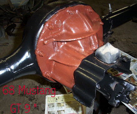
The most popular rear end around is no doubt the Ford 9 inch unit, it is used by restorers, street rodders and racers alike, regardless of what brand of car the axle is going in. Many custom made axle housings for the GM boys utilize the 9 inch Ford, even though they hate to admit it. Ford used the axle from around the 1957 model year right up until the early 1980’s in cars and trucks. It was not the only axle used, but was by far one of the best. Variations by Ford exist in the size of the outer axle bearings in the housings and carriers both, as well as with the spline count on the axle shafts. Generally most cars received the small axle bearings and 28 spline axle shafts. Exceptions to this were the ultra Hi performance Boss 302’s, Boss 429’s, 427’s, 428 CJ/SCJ and the 429 cars which received the 31 spline carriers and axle shafts. Some of the heavier cars like the Galaxies,later Tbirds and mid 70’s Torinos also received the larger wheel bearing housings.The trucks varied more, early half ton trucks got the 28 spline axles and carriers, while sometime in the early 70’s the switch was made to mostly 31 spline axles and carriers for trucks while some vans remained 28 spline. Most of the later trucks also received the larger axle bearings housings.One exception to this was the Bronco’s from 1966 to 1977, they stayed with the 28 spline units and in mainly small bearing housings, although some of the later 74-77 it seems started getting the heavier axle housing with large bearings. A small bearing housing can be differentiated from a large bearing housing by the size of the nuts and thread used to retain the brake backing plates to the housing, the small bearing housings use 9/16 socket size nuts with 3/8” fine thread, while the larger bearing use 3/4” socket size and 1/2” fine thread. Gross Vehicle Weight ( GVW ) would determine which axle housing many cars and trucks received.(Note-See New bearing information under Housing Section Below-updated 12/04) Because many one half ton trucks continued to utilize the 9 inch (both 2 wheel & 4 wheel drives) right up until about 1982 these housings are by far the most abundant(Note:Some 1/2 ton Vans and Trucks used the 9 inch right up until about 1985/86 or so in limited quantities), and with many 1973 to 1979 pickups to still be found on the road and in junk yards,these are very plentiful. And since the “Limited slip” or Locking rear end (often referred to as a “POSI”) came to be a popular option starting in the early 1970’s, many of the units found today at car swap meets and shows are the units pulled from trucks with the 31 spline carriers with the “Traction Loc” style posi unit. The actual car posi units which were primarily 28 spline carriers can be much more difficult to locate since the supply is limited to the few cars and early Broncos (and some early trucks) which received them.When it comes down to actual shafts as well, since the truck lug pattern in most cases differed from the car, and due to the bearing size differences, 28 spline car axle shafts are much more abundant than car 31 spline axle shafts, and often aftermarket shafts have to be purchased if one wants to use a truck 31 spline carrier in a car. The carrier case I see frequently is the C7AW-E, it is the one commonly found in the trucks,vans and cars throughout the late 60’s and the 1970’s, right up until around 1985 in some truck applications. I am not sure if this “E” version of the case came into use in 1967 or in subsequent years, but it is by far the most abundant case being used in both full size Ford cars and trucks throughout the 1970’s. I have heard that it has a higher nodular iron content and better casting than the earlier single ribbed cases it replaced and that is why it remained in use so long, and the double ribbed N case was no longer needed for passenger car/truck applications (this also coincided with the demise of most performance engine options in the 70’s)- I have never seen this substantiated however. Most carriers I have seen for sale at swap meets/ car shows are this C7AW-E case which leads me to believe they were pulled from trucks and cars from the 1970’s. Axle housings as noted in the examples below also evolved over the years, the earlier housings used in cars from 1957 to mid 1960’s tended to be the weakest and had abrupt ending butt welded carrier centers to tubes and a smooth backside. Later housings appeared in 1966 with the familiar “Hump” in the backside middle and stronger tubes.The later truck housings received even beefier center carrier housings and tubes and this style of center carrier housing is best suited for drag cars or narrowed rear ends in my opinion due to the added strength in the middle (have heard it referred to as the “Banjo style”). In general the early housings are ok for the average street performance cars. The popular early swap being the 57 to 59 Ford for the 65/66 Mustang – this will also be the narrowest stock Ford 9″ application (about 52″ housing flange to flange).I haven’t completed an axle housing width chart yet, but here is what I can tell you about some that I have seen, they often group Mustangs and Fairlane axle housings together as often it is true they are the same width, but I can tell you for a fact, the distance between spring perches is different between Mustangs and Fairlanes.Spring perches must be cut and re-welded inorder for the swap to be performed. The “rough” widths I keep in mind for Mustangs are the following: 52” for 1965 to 1966 (the same width as 64-65 Falcons and 62 to 65 Fairlanes)(as in the Mustang line, most however never received a factory 9 inch), 54” for 1967 to 1970 (same as 66 to 69 Fairlane,Torino,Comet & Cyclone non station wagons)cars with 351 and up engines received 9 inch units-as did some 302 4V cars-(mainly GT’s in 68 with optional gear ratios)* and 56” for the 1971 to 1973 Mustangs/Cougars- (cars with 351 engines and up receiving the 9” housings).Keep in mind as mentioned, the Fairlane spring perch distances were not the same as the Mustang. All the Galaxies I have seen from throughout the 1960’s used the 9 inch rear, regardless of engine size.
How to Identify some typical Ford Centers
Let’s start with the 9″
First off, the 9” is a removable carrier type rear end, it shares this design in common with it’s baby brother the 8”, while the 6 ¾”, 7 ¼’, 7.7” , 8.8” and Dana rears also used in Fords are integral carrier types. Both GM and Mopar also had earlier removable carrier type rear ends, they are no where near abundant as the Ford. Removable carrier means these are front loading differentials, they have no cover / inspection plate on backside-the 8.8’s etc are considered rear loaders. When a gear ratio change is desired, a entire carrier assembly (previously assembled) can quickly be installed by simply pulling the axles and drive shafts, then undoing the ten center retaining nuts.
Quick ways to indentify a 9″ visually:
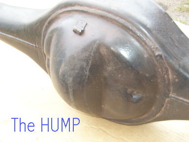
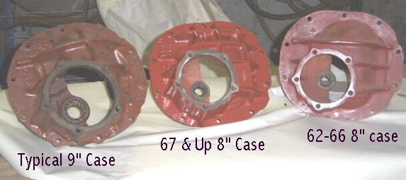
From rear of car look for a large center hump in middle of backside center section (post 66 models), in general a round appearance, it is a 9”.See photo above.
From front side look at the bottom two center retaining nuts, if a socket cannot access them to remove, only a wrench, then it is a 9” See photo below.
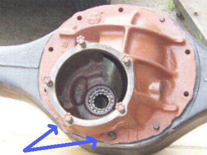

There are several distinct case types used over the years for the 9” carrier (shown above are the 3 basic)…lets start at the beginning with the infamous WAR case…

I have heard various stories as to the reliability of the WAR marked cases, some say avoid them like the plague, others say this is false.Here is what I understand, while having the extra ribbing like the later N case, they do not have the nodular iron content and are prone to cracking at the bearing support.They seem to have been used on the 57 to 60 Fords from casting dates I have seen.
Another early case, the WAB was similar to the WAR case with the double rib and lower nodular content. I do not have a photo example at present.I believe this case utilized the larger 3.063 side bearings.
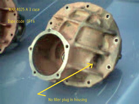
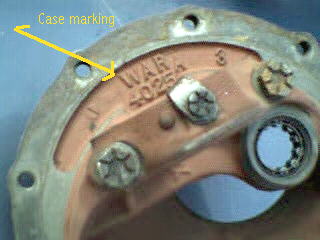

The C7AW-E case seems to have been the standard case in use for quite sometime, have found them with date codes up to 1981.Other standard cases encountered: C1AW-4025-C,C4AW-4025-A
Some standard cases are also machined to take the larger 3.063”(the C7AW-G mainly) side bearings, most cases however (including N cases) will take the 2.892” side bearings. Aftermarket spools and cases are available that accommodate even larger bearings-3.250″ and 3.812″, but Ford used just the two sizes from what I have seen.The carrier I have seen with the 3.063″ larger side bearings is the C7AW-G marked single ribbed case, it came from a late 60’s Galaxie.Have heard that the case C4AW-4025-C is also a large bearing single ribbed case.
[ ]
THE N Case vs WAR Case
“Standard or WAR cases, were cast in gray cast iron which has a grain structure that does not have the best shear strength characteristics. The N stands for nodular iron, which is made by adding magnesium to molten iron. What this does is change the grain structure from flakes to nodules – much stronger and less likely to fail under shear load.” – contributed by Paul Bartus
The case of course most desirable is the N case, first used on the 427 Galaxies around 64-65 I believe.They are most often found behind the later 428CJ and 429CJ cars.From what I have seen don’t expect to find them in 390 or 289 Hipo cars.The N cases went with 31 spline centers and are for rugged duty.And believe it or not, they were also used in some FE equipped Ford 1/2 ton 4X4 pickups!
Here’s a quick tip someone sent me for spotting an N case while installed in a housing, look to the area just to the right of the carrier fill plug on side of case, on an “N” case an only an “N” case this area will be filled in-flat cast metal. On the “WAR”, “WAB” and standard cases there will always be a cast in recession that forms a pocket. The 9 3/8″ also has this area filled in-but it has the bent down horizontal rib end.Compare the various photos on page and you should see what I am talking about.

Here is the early N case, the C4AW-B casting, which can either have the N or not.Some N cases will also have the bearing caps marked with an “N”, some do not.
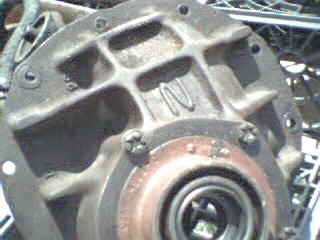
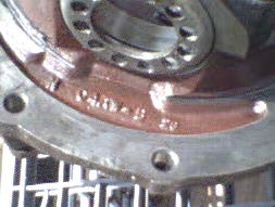
Have also viewed a N case marked with an “N” with a C2AW-4025-A casting number,it was used in conjunction with a C5AW-4668-C Daytona pinion support.Case was double ribbed, this casting number is not listed in my books or references, will have to do further research regarding this one.

Pinion Supports
Standard Supports


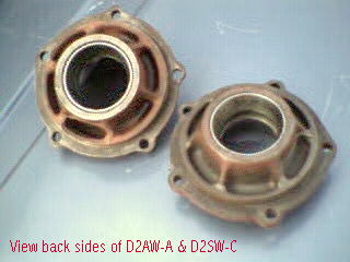
Other standard pinion supports encountered: WAT B2(on a WAR case),C0AW-A,C5AW-4668-A,C6AW-4668-A,C7AW-C(guarded), D2AW-A (guarded) and a D2SW-4668-C(marked with the 4668).The D2SW-C seems to be the most common encountered through 1979 on the C7AW-E cases I have viewed.
Daytona Supports


Photo below shows a the D2OW-C hooded daytona pinion support which may have been the last Ford production Daytona support from what I have seen.
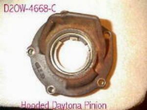
Daytona pinion supports are found in conjunction with N cases, they have the same size outer bearing as the standards supports, but the inner bearing is much larger, and the inner webbing much stronger. Visually on the outside look for a flat surface with no raised areas around the mounting holes (this is true for the non-guarded/hooded supports only). Photo below shows a standard support on left and a D2OW-4668-C Daytona support on right with their respective bearings.The D2OW-4668-C is the only Daytona support that I have seen to have the guard/hood cast in. Inner bearing number for Daytona support (D2OW-C) is HM89443, with a HM89410 race.Aftermarket supports of equal or greater strenth (larger bearing sizes) are available.Earlier Ford daytona pinion supports: C5AW-4668-C, D10W-4668-A .
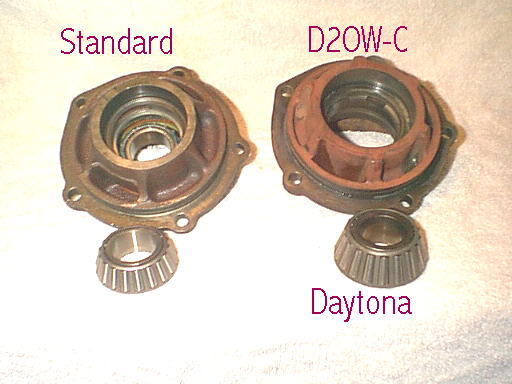
Photo courtesy of Shawn Reim
A 9 1/2″ ???
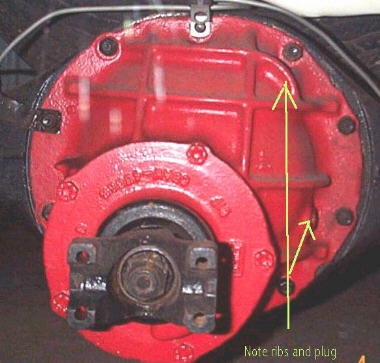
Here is something else you may run across, a 9 3/8″ ring gear housing(sometimes called a 9 1/2″ Ford carrier),I don’t know much about them, but looking in the book they appear to have come in the larger Lincoln and Mercury vehicles.Note casting number C8AW-4668-B on pinion support and the double ribs(spaced further apart) with the end bent down on one.From what I understand most parts from these rears do not interchange with the 9 inch carriers.I have heard they can be installed in a 9″ housing if the housing is notched for the wider gear and the gasket for the 9 3/8″ is used (bolt pattern is supposedly the same).I have started to see a few of these in some Ford pickup applications, mainly 4X4 with a trac loc option and FE motors.The truck applications seem to have some better ratios than the passenger car applications.All the applications of the 9 3/8 I have seen have been 31 spline.
Here is some 8″ info:
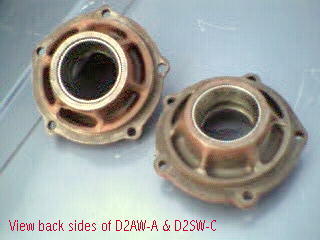

The casting number should be C2OW-4025-F, NOT C2DW listed for the case.Another later 8″ pinion support with guard built in that I have seen had casting number C6OW (the 6 however may have been a 5-this support came out of a 65-66 mustang center).
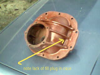
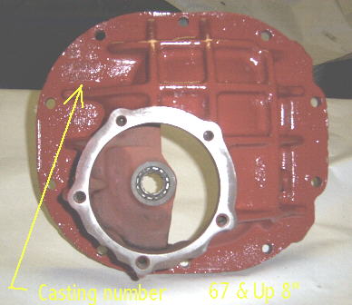
Later improved carrier for the 8″ found in 67 and up
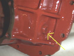

Note the presence of fill plug, and that the casting number is moved to the outside of case, while other previous 8 and 9 inch carriers it has always been on the inside.The number here is the familiar C7OW-4025-A.
Housing Types and Sizes
Visually Spotting the 9″ and 8″ Axle Housings
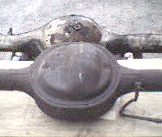
Shown above is the typical 1967 and up 9″ (lower) and pre-1967 8″ housing (upper).Note no fill plug on back of the 67 and up housing, this is true for the 67 and up 8 inch housings too.Earlier housings, like the 65-66 Mustang 8″ pictured have the fill plug in the back, this is true for the earlier 9″ as well.
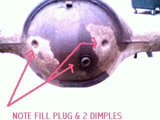
One of the ways many people spot a 9″ rear end in the car is by looking for the hump in the center of housing, this is not always the best way, as 9″ housings made prior to sometime in 1966 do not have the this large center protrusion.The one shown above is out of a 63 Galaxie, note its roundish appearance, two dimples and fill plug in housing back.
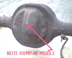
Here is the housing style familiar to most, note the large center protrusion or simply the “hump” in the middle.Housing also has the two dimples, but note lack of fill plug.This housing is out of an early Bronco.
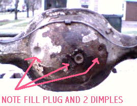
The little brother to the 9″ housing is the 8″ housing, note its more oval appearance when compared to the above two 9″ housings.This one is out of a 65-66 Mustang, note the two dimples and fill plug.
Housings and Bearings, etc.
This is a new section with some recently obtained specific information I have gathered on the types of bearings and housings used by Ford. For the nine inch there are are two bearing sizes used for housing ends, the smaller eight inch used just one. However, for the nine inch (as assembled by Ford)there are 3 different bearings- one small and two large. The two large are the same size ( I.D. / O.D specs), but different types of bearings- one is the traditional sealed ball bearing, while the other is the oil bathed roller bearing and race type.The eight inch and most nine inch housings used the small bearing- including the 31 spline CJ cars, Mustang Hi-performance etc.. This bearing was of the sealed ball bearing type, # RW207CCRA (specs: 1.378″ I.D., 2.8246″ O.D. by 0.8449″ width). Early Galaxies and Broncos and some mid 70’s Torinos used the large type sealed ball bearing, which meant they had a large tube housing end, bearing # 88128-RA (specs: 1.5312″ I.D., 3.1496″ O.D. by width). The second type of large bearing (roller type) was used in later pickups and larger Ford cars, bearing # A20 (specs. 1.530″ I.D., 3.1530″ O.D.), the seal was on outside of bearing. Because of the two different size bearings used in the 9 inch, there are also two (actually three) different backing plate mounting patterns as well. The standard small bearing has an approximately 3 1/2″ (horizontal)by 2″ (vertical) pattern with 3/8 inch mounting hole diameter, while the large bearing is 3 1/2″ by 2 3/8″ respectively with 1/2 inch hole size. Some of the mid 70’s Torinos used a slightly different plate with a spacing of 3 9/16″ by 2″ respectively with 3/8″ hole size. Good news for restorers and rodders out there is that there are adaptor bearings available to ease the swapping of axle shafts and housings that would have originally been potential problems. There are bearings made to swap the larger 31 spline shafts that may have been shortened into small bearing housings (spces- 1.531″ I.D. by 2.834″ O.D.)-it is available from aftermarket suppliers. I think there is also a bearing that will do the swap the opposite- swap typically small bearing shafts into a large bearing housing, the info I have found is that the BCA 511004 will do this, haven’t tried it myself yet, but is has the correct 1.378″ I.D. by 3.1496″ O.D. .
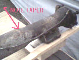
Another area of concern when swapping axle housings into earlier Mustangs (65-66 models especially)is the diameter of the outer axle tube.Note the taper on this 8″ 65-66 Mustang housing, a smaller U bolt and lower shock plate were used originally with these cars.The HIPO 289 cars were the only 65-66 Mustangs to recieve factory 9″ axles, the tubes are tapered as well at the end to utilize the same lower shock plate as the regular 65-66 Mustangs.
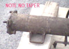
Notice this axle tube has no taper at end,as is typical for most housings.A typical early Mustang swap is a later Granada housing, were the non-tapered tube can become an installation problem at times.
Measuring Housings


A note on measurement of housings, a couple of things need to be considered.First overall width, second spring perch location (or modification for coil spring use).When I talk about overall width measurement here on this page, I am referring to the measurement from the inside housing flange side to side.For example, the typical early 65-66 housing is about 52″ (actually more like 52 1/4″-I am just rounding for convience here). You can also measure axle flange to axle flange (this is the flat surface brake drum rest on when installed on axle shaft), generally this adds about 5 inches to the housing flange to flange measurement- i.e. the 65/66 Mustang measurement would be about 57 inches if measured this way. Spring perchs are measured by their center to center distance from each other, and by the distance from the housing flange end. For example, all 65 to 73 Mustang spring perches are located slightly over 43 inches apart – physically you could bolt a 73 Mustang housing which is over 56 inches wide into a 65 Mustang body with a normal 52″ wide housing because the spring perches are in same location. The wheel would however obviously extend well outside the fender. What changed was the distance from the spring perch to the outer housing flange- it grew two inches per side in this case, 4 inches overall.
Housing Ends/Brake Backing Plates
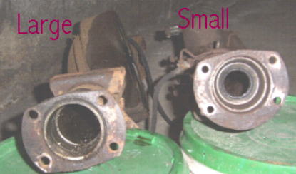
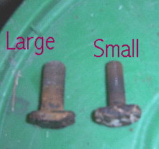
Shown above are a large bearing housing (to left) and a small bearing (right), the bolt spacing is different between the two as is the center hole opening, thus they utilize different backing plates for the brakes. Most small to medium size cars utilized 10″ rear brakes, in 1 3/4″, 2″ or 2 1/2″ widths. The larger cars and many trucks utilized 11″ brakes, typically 2 1/4″ width. Finding the small housing 11″ backing plates can be a little more difficult than some of the other applications. Another popular alternative is to upgrade to 10 X 2.5″ . Photo below shows the two different size backing plate mounting studs- large and small used with respective size bearing housings.
Axle Shafts
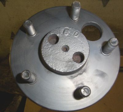
Shown above is a 31 spline shaft end in a 69 Cyclone CJ
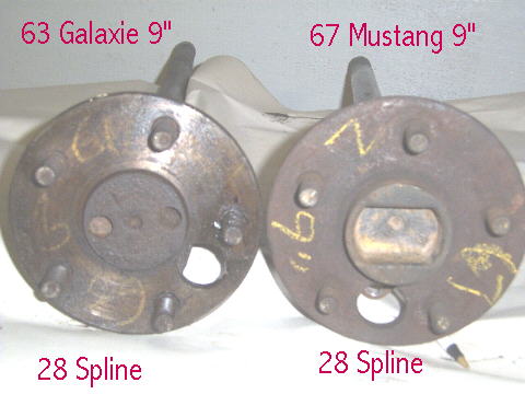
Ford used either 28 spline or 31 spline axle shafts with the nine inch, the eight inch came only in 28 spline, as did the majority of nine inch car applications.For the most part eight inch and nine inch car axle shafts will interchange between housings of the same width,spline count and bearing size (ie. 8″ 67 Mustang 28 spline axle shafts will work in 9″ 67 Mustang housing, etc.).A method to identify 28 spline axle shafts can be by looking at the center brake hub area, a rectangular slot in the center will indicate 28 spline axles.The 31 spline axle shafts will have a different appearance, with one small center chamfer and two outer holes in the center hub, however, 28 spline shafts can also appear like this to, so it does not always indicate 31 spline shafts (see photo below). Early axle shafts of the 28 spline variety cannot be shortened, due to either a reduced diameter between spline end and bearing end (early Mustangs,Fairlanes, Falcons etc.), or because of a tapered shaft which doesn’t allow for re-splining (early full size).It appears starting around 1967 the 28 spline shafts became more solid and the shaft diameter increased along the entire length, so shortening is possible and they can be be resplined to their original 28 count.Most 31 spline shafts can be shortened and resplined with no problems.
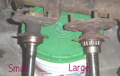
(above)Small bearing shaft on left, large bearing shaft on right
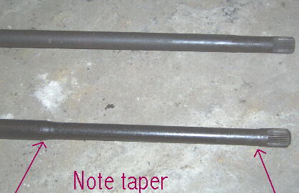
Note the early axle shaft with tapered middle section, these cannot be shortened or resplined
Rear Axle Tags
Rear axle tags if present on your housing can aid in identifying what is behind your center for gears,splines etc.Ford has changed the tag over the years, but generally the appliction number-which begins with the W on line one, the gear ratio and date code are always given.Tags are generally found attached to the passenger side of carrier assembly secured by one of the nuts on the housing studs.Here are some examples I have:
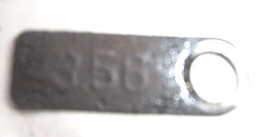
Above is the earliest style tag I have seen used (mainly on 57/58 Fords), it is quite simple – just the ratio given, here 3.56.
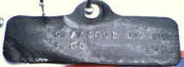
Another early style tag used by Ford, this one is off a 62 Galaxy with a 3.00 open 9 inch.Tag reads C2AA4001 DV 100,second line:: 3.00 1MA

Here is a common Mustang tag WCZ-V identifies it as a 67-70 Mustang and 67-68 Cougar 8″ rear with 2.79 ratio, open.Note no L between 2 and 7 on second line.
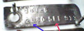
A “posi”, equa-lock or traction lock rear is identified by an “L” in between the 1st and 2nd digits of the ratio given on the second line of tag.Here is a 2L80 ratio with tag number WDJ-B,which corresponds to a 8 inch used in 65-66 Mustangs.
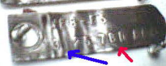
This tag is off an open 3.25 ratio 66-70 Fairlane or 67 to 69 Comet with an open 9 inch differential.Note date code of 7BD ( 7= model year:1967,B= Month:February and the D= week: 4th week of Feb.1967)
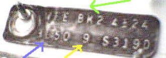
Ford changed the layout of the tags sometime in the early 70’s or late 60’s, here is a WFE-BK2 tag, followed by a date code of 4E24 (April 24,1974), the second line now gives besides the ratio-here a 3L50, the ring gear actually used inside-this one is a true 9″ gear.This tag is off a 74 Ford truck.
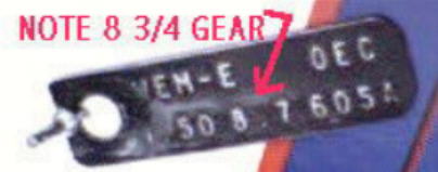
Here is an example tag of a 9 inch that isn’t quite up to the full measure,it is a 3.50 ratio, but followed by that are the numbers 8.7 which denote that this carrier is sporting a ring gear of an actual 8 3/4 inch diameter.This one is off a 1970 Bronco, built 3rd week of April 1970.This would have been a 28 spline unit when checked in manual.
How to identify a “Posi”
The two basic types of “posi” units (posi is the G.M. name for its positive traction system which has been become a part of the nomenclature) are the early Equa lock and the subsequent Traction lock units ( I will refer to them here as “spools” to simplify things). I am not exactly sure when the Equa-locs first appeared, early units are scarce – I haven’t seen many prior to 1964/65 and these are quite rare.From what I have seen the Equa locs were used up until 1969, which is when I believe the Traction Loc units first appeared. There are visual and internal differences between the two spools and most parts do not interchange.
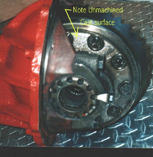
Shown above is an example of an equa loc in its carrier, you will note the recessed bolt holes and 5/8” headed bolts, as well the rough cast appearance of the cover assembly, it is not machined as it is in the Traction Loc units.
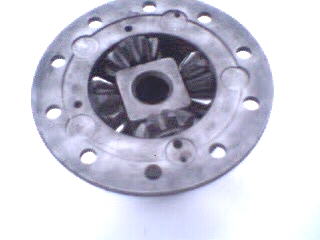
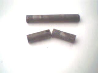
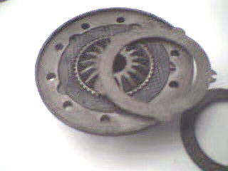
Internally the number of clutch disc and plates differs between the equa loc and trac loc spools, the equa loc having only 3 fiber plates and 4 steel with one large belveder spring applying force.The trac loc unit utilizes 4 fiber plates and 5 steel plates, with 4 smaller springs applying force.Both equa lock and trac loc units were available in 2 pin and 4 pin varieties, in either 28 spline or 31 spline versions.The four pin 31 spline unit would be more commonly found as a trac loc piece. The four pin being the heavier duty unit utilizing 4 spider gears vs just two in the two pin variety (as noted in figure above a four pin variety will have actually just 3 pins and a two pin will in reality just have 1 pin- the number of spider gears is actually what is being referred to).Shown below are the internals of a four pin equa loc, note the five “fingers” on the steel clutch plates-the tiny circular tabs on outer edge- (trac loc units will have only 4).
The traction loc
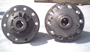
Shown above is an open 28 spline spool (on left) and a traction loc “Posi” 28 spline 2 pin spool ( to the right).
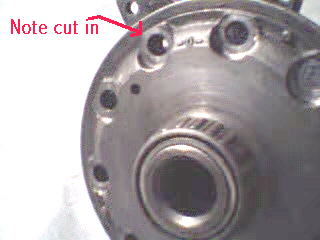
Here is a close up of the trac loc spool, note recessed bolt holes through cover for holding ring gear on.
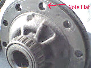
Notice the flat surface around holes on the open spool.
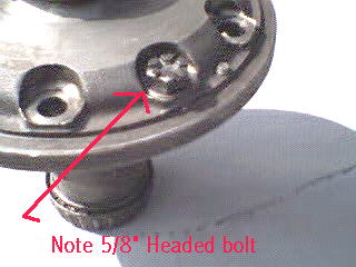
The heads of the bolts which pass through cover and fasten ring gear to the spool are also smaller on the trac loc piece 5/8” socket size, and they use a thin metal washer.
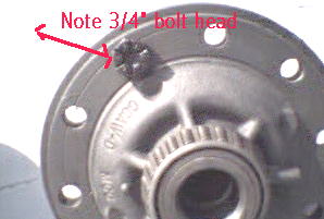
The bolt retaining ring gear on the open spool is 3/ 4” socket size, no washer used.
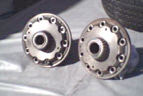
Above are a 28 spline 2 pin traction loc unit and a 31 spline 4 pin trac loc unit, notice anything wrong?
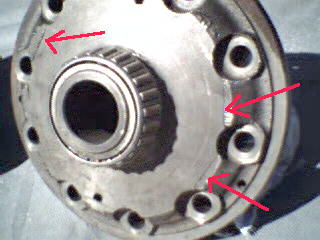
The arrows are pointing to the cracks in the 31 spline unit removed from an N case carrier.
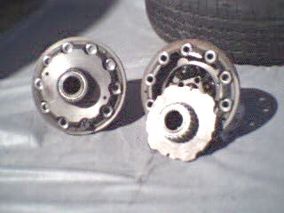
Unfortunately this is the end result, a destroyed posi unit, this is even the improved cover – D0O part number, earlier units were even more prone to cracking here, thus the necessity for the Detroit Locker units used behind many of the higher performance applications.
Gears, Yokes etc.
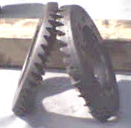
Here are two nine inch ring gears side by side, one from a 3.00 ratio (thinner gear), the other from a 3.50 ratio (thicker).An easy way to spot a nice ratio after a while is by visual id.-the thicker the gear the better the performance ratio, thinner the gear= less performance, more fuel economy and better highway performance.
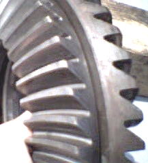
These two gears are the same ratio- 3.00, but one is only 8 3/ 4” diameter, the other a true 9”.When gear is installed in the case, a true 9″ ring gear will have very little clearance between housing and large gear (most noticable at bottom), while an 8 3/4″ setup will have almost enough room to put your finger tips into between gear and case (but don’t due it- it can hurt).Don’t feel slighted if you find you only have an 8 3/4″ setup, they are plenty strong, Ford used them behind the HiPo 289 applications in many Mustangs and others.
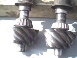
Can you spot the difference in the above two pinion gears? Both are 10 tooth gears taken from 3.50 gear ratios, but one has been used behind a Daytona pinion support with the larger inner bearing (see above sections for discussion on Daytona pinion support identification).Note the larger bearing on support to the left.
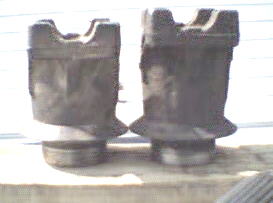
These two yokes are quite similar and take the same U joint, except the shorter one is used with the larger bearing Daytona Pinion used in an N case. I believe the shorter yoke was necessary due to the added size of inner bearing.When installed on there respective carriers, supports equal out to approximately same height.I am told that the standard yoke can be machined down to work with the Daytona pinion.
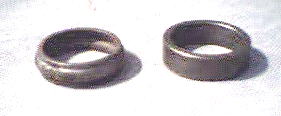
Crush sleeves are used when setting up most 9 inch carriers to set bearing load, but on the N case with Daytona pinion a non-crush solid spacer is used, shown above are the two side by side (solid spacer on right).
This page is far from complete,but it is put together out of my experiences (with the help of some personal friends and internet member contributions) in searching out Ford rear ends over the last few years .It will hopefully be a good visual guide to the various differentials used in the older Fords.I will most likely add sections as time permits and expand upon some of the above as I gain more insight.Eventully I may add some of the smaller integral carrier information as well.
